
CM550-22F — Wireless remote monitoring and control terminal
Source V1.2 · Technical review edition · PDF
CM550-22F
A remote monitoring and control RTU with Ethernet, multiple serial interfaces and sensor inputs. The official interface table lists SDI-12, a tipping-bucket rain-gauge input and analog inputs for telemetry integration.
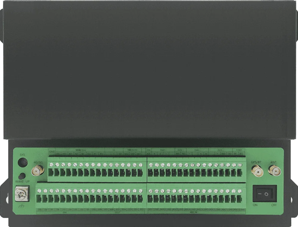
Product photography. Open full image ↗
Options vary by model, hardware revision and firmware.
| Ethernet | 1 × 10/100 Mbps Ethernet port |
|---|---|
| Serial interfaces | 2 × RS232 and 2 × RS485 |
| Analog inputs | 8 × 16-bit analog inputs; 4–20 mA, with optional 0–5 V configuration |
| Sensor interfaces | 1 × SDI-12; 1 tipping-bucket rain-gauge input |
CM550-22F — Wireless remote monitoring and control terminal · Source V1.2 · Source p. 1
| CM550-22F | Connection: Ethernet and terminals; Cellular: 2G/3G/4G/5G; RS232: 2; RS485: 2; Display: None |
|---|
CM550-22F — Wireless remote monitoring and control terminal · Source V1.2 · Source p. 4
| Network access | APN/VPDN; CHAP/PAP/MS-CHAP/MS-CHAPv2 authentication. |
|---|---|
| LAN protocols | ARP and Ethernet, as listed. |
| Link detection | Heartbeat probes, automatic reconnection. |
| Watchdog | Operating self-check and fault self-recovery. |
CM550-22F — Wireless remote monitoring and control terminal · Source V1.2 · Source p. 4
| Platforms | Hydrology/water-resource management; environmental monitoring; Alibaba Cloud and other IoT platforms; centralized management and batch configuration. |
|---|---|
| Protocols | Modbus TCP; Modbus RTU; SZY206 water-resource monitoring data-transfer protocol; SL651; SL/T 427 water-resource monitoring data transfer; HJ212 environmental protocol. Formal editions and supported subsets need confirmation. |
CM550-22F — Wireless remote monitoring and control terminal · Source V1.2 · Source p. 5
| Ethernet | One 10/100 Base-T; source IEEE 802-3 / 802-2 notation; 1.5 kV isolation. |
|---|---|
| Serial | Two RS232 and two RS485; 7/8 data bits; 1/2 stop bits; none/odd/even parity; 300-4000000 bit/s; no, hardware or software flow control. |
| Rain / SDI / pulse | One tipping-bucket rain gauge; one SDI-12; one pulse count input, up to 1 kHz. |
| Analog inputs | 8 channels; 16-bit ADC; 4-20 mA, optional 0-5 V voltage input. |
| Digital inputs | 8 optoisolated channels. Logic 0: wet contact 0-3 V DC or closed dry contact; logic 1: wet contact 5-30 V DC or open dry contact. |
| Digital outputs | 8 optoisolated channels. Source maxima: 30 V DC switching voltage, 50 mA switching current, 150 mW switching power. Limits are not assumed simultaneously achievable. |
| Relay outputs | 4 optoisolated channels. Source maxima: 250 V AC / 30 V DC, 1 A and 30 W. Confirm the load category and combined ratings before use. |
| Controlled supplies | 5 outputs, listed nominally 12 V / 1 A with overcurrent protection. Pin table also says outputs follow equipment supply voltage; confirm regulation and total/per-output limits. |
| Antenna | SMA female, 50 ohm; optional 3/5/10/15 m extension cables. |
| SIM/UIM | 1.8/3/5 V flip-type SIM socket with 15 kV ESD protection. Another section calls it a push-type interface; confirm supplied hardware. |
| Power connector | Industrial terminal with reverse-polarity and overcurrent/overvoltage protection. |
| Indicator / wake | SYS indicator; button wakes the unit from sleep. |
CM550-22F — Wireless remote monitoring and control terminal · Source V1.2 · Source p. 6
| 5G SA/NSA | NR n1/n2/n3/n5/n7/n8/n20/n28/n41/n66/n71/n77/n78/n79. |
|---|---|
| 5G source rates | DL 3.4 Gbit/s / UL 350 Mbit/s; modem capability claim, not measured RTU/application throughput. |
| Wireless module | Industrial wireless module; actual modem/configuration must be confirmed. |
| TDD radio group | LTE TDD 2600/2300 MHz; UMTS 2100/900 MHz; GSM 850/900/1800/1900 MHz; receive diversity UMTS 2100/900 MHz. |
| FDD radio group | LTE FDD 2600/2100/1800/DD800 MHz (source notation retained); UMTS 2100/900 MHz; receive diversity UMTS 2100/900 MHz. |
| Source encoding/mode list | LTE/UMTS/HSPA+/HSDPA/HSUPA/WCDMA/EDGE/GSM. |
| TDD-group data rates | LTE TDD DL 68 Mbit/s / UL 17 Mbit/s; DC-HSPA+ DL 42 Mbit/s (category 24); HSPA+ DL 28 Mbit/s (category 18); HSDPA DL 14.4 Mbit/s (category 8); HSUPA+ 5.76 Mbit/s (category 6; source labels DL, direction Confirmation required); WCDMA CS UL/DL 64 kbit/s; WCDMA PS UL/DL 384 kbit/s. |
| FDD-group data rates | LTE FDD DL 100 Mbit/s / UL 50 Mbit/s; DC-HSPA+ DL 42 Mbit/s (category 24); HSPA+ DL 28 Mbit/s (category 18); HSDPA DL 14.4 Mbit/s (category 8); HSUPA+ 5.76 Mbit/s (category 6; source labels DL, direction Confirmation required); WCDMA CS UL/DL 64 kbit/s; WCDMA PS UL/DL 384 kbit/s. |
| Transmit power | LTE 23 dBm; WCDMA/HSDPA 24 dBm. |
| Receive sensitivity | <-109 dBm. |
| services | Data, voice, SMS and fax; verify service support on the ordered modem and regional network. |
CM550-22F — Wireless remote monitoring and control terminal · Source V1.2 · Source pp. 7-8
| CPU | Industrial high-performance 32-bit embedded processor. Feature section identifies Cortex-M4, up to 120 MHz. |
|---|---|
| SRAM / program flash | 256 KB / 512 KB. |
| Data flash | 32 MB; expandable to 64 MB. |
| External storage | 32G TF card as listed. |
CM550-22F — Wireless remote monitoring and control terminal · Source V1.2 · Source pp. 7-8
| Input | 7-32 V DC in design/specification; another reliability paragraph says 5-36 V. Confirmation required. |
|---|---|
| Adapter | 9 V DC / 1.33 A |
| Communication current | 400 mA at 9 V DC |
| Registration peak | 1.0 A at 9 V DC |
| Standby | <200 mA at 9 V DC |
| Operating | -35 to +75 °C |
| Storage | -40 to +85 °C |
| Humidity | 95% RH, non-condensing. |
CM550-22F — Wireless remote monitoring and control terminal · Source V1.2 · Source pp. 7-8
Certification scope and test conditions depend on the selected model. Request the applicable documentation.
| ESD | EN 61000-4-2, level 3 |
|---|---|
| Radiated field | EN 61000-4-3, level 3 |
| Electrical fast transient | EN 61000-4-4, level 3 |
| Surge | EN 61000-4-5, level 3 |
| Conducted disturbance | EN 61000-4-6, level 3 |
| Power-frequency magnetic field | EN 61000-4-8; horizontal/vertical 400 A/m, labeled level 3 in source. Confirm test level/report. |
CM550-22F — Wireless remote monitoring and control terminal · Source V1.2 · Source pp. 7-8
Certification scope and test conditions depend on the selected model. Request the applicable documentation.
| Enclosure | Metal, shielding, lightning design, enclosure/system isolation, source IP30. |
|---|---|
| Dimensions | 210 x 147.4 x 32.8 mm excluding antenna; source refers other products to appendices. |
| Weight | Approx. 900 g excluding antennas, mounting parts and packaging. |
| Shock / vibration / drop | IEC 60068-2-27 / IEC 60068-2-6 / IEC 60068-2-32. |
| Domestic claims | MIIT network access permit, 3C, EMC, Ministry of Railways CRCC and Mo'er high-/low-temperature testing. |
| Overseas claims | CE, FCC, E-mark and RoHS. No certificate numbers or exact variant scope supplied. |
CM550-22F — Wireless remote monitoring and control terminal · Source V1.2 · Source pp. 9-10
| 1 / 2 | Signal: DC+ / DC-; Source function: Supply input positive / negative. |
|---|---|
| 3 / 4 | Signal: RS232-2 TXD / RXD; Source function: Second RS232 transmit / receive; default 115200 bit/s. |
| 5 / 6 | Signal: + / -; Source function: Controlled supply for RS232-2. |
| 7 / 8 | Signal: RS485-2 B / A; Source function: Second RS485 B / A; default 115200 bit/s. |
| 9 / 10 | Signal: - / +; Source function: Controlled supply for RS485-2; note polarity order. |
| 11 / 12 | Signal: RS232-1 TXD / RXD; Source function: First RS232 transmit / receive; default 115200 bit/s. |
| 13 / 14 | Signal: - / +; Source function: Controlled supply for RS485-1; note polarity order. |
| 15 / 16 | Signal: RS485-1 B / A; Source function: First RS485 B / A; default 115200 bit/s. |
| 17 | Signal: ADC_POWER / ADC; Source function: Controlled positive supply for analog-input equipment. |
| 18 | Signal: Rain1; Source function: Pulse count. |
| 19 | Signal: GND; Source function: Digital-input ground. |
| 20 | Signal: Rain2; Source function: Rain-gauge input. |
| 21 | Signal: SDI; Source function: SDI-12 data. |
| 22 / 23 | Signal: + / -; Source function: Controlled supply for SDI-12. |
| 24 / 25 | Signal: K1+ / K1-; Source function: Relay 1 output pair. |
| 26 / 27 | Signal: K2+ / K2-; Source function: Relay 2 output pair. |
| 28 / 29 | Signal: K3+ / K3-; Source function: Relay 3 output pair. |
| 30 / 31 | Signal: K4+ / K4-; Source function: Relay 4 output pair. |
| 32 | Signal: GND; Source function: Spare supply-input negative. |
| 33 / 34 | Signal: GND / ADC0; Source function: Analog-input ground / channel 0; 4-20 mA in this pin table. |
| 35 / 36 | Signal: GND / ADC1; Source function: Analog-input ground / channel 1; 4-20 mA in this pin table. |
| 37 / 38 | Signal: GND / ADC2; Source function: Analog-input ground / channel 2; 4-20 mA in this pin table. |
| 39 / 40 | Signal: GND / ADC3; Source function: Analog-input ground / channel 3; 4-20 mA in this pin table. |
| 41 / 42 | Signal: GND / ADC4; Source function: Analog-input ground / channel 4; 4-20 mA in this pin table. |
| 43 / 44 | Signal: GND / ADC5; Source function: Analog-input ground / channel 5; 4-20 mA in this pin table. |
| 45 / 46 | Signal: GND / ADC6; Source function: Analog-input ground / channel 6; 4-20 mA in this pin table. |
| 47 / 48 | Signal: GND / ADC7; Source function: Analog-input ground / channel 7; 4-20 mA in this pin table. |
| 49 | Signal: DO1; Source function: Digital output channel 1. |
| 50 | Signal: DO2; Source function: Digital output channel 2. |
| 51 | Signal: DO3; Source function: Digital output channel 3. |
| 52 | Signal: DO4; Source function: Digital output channel 4. |
| 53 | Signal: DO5; Source function: Digital output channel 5. |
| 54 | Signal: DO6; Source function: Digital output channel 6. |
| 55 | Signal: DO7; Source function: Digital output channel 7. |
| 56 | Signal: DO8; Source function: Digital output channel 8. |
| 57 | Signal: GND; Source function: Digital-output ground. |
| 58 | Signal: DIN1; Source function: Digital input channel 1. |
| 59 | Signal: DIN2; Source function: Digital input channel 2. |
| 60 | Signal: DIN3; Source function: Digital input channel 3. |
| 61 | Signal: DIN4; Source function: Digital input channel 4. |
| 62 | Signal: DIN5; Source function: Digital input channel 5. |
| 63 | Signal: DIN6; Source function: Digital input channel 6. |
| 64 | Signal: DIN7; Source function: Digital input channel 7. |
| 65 | Signal: DIN8; Source function: Digital input channel 8. |
| 66 | Signal: GND; Source function: Source calls this digital-output ground in the DIN group. Ground role Confirmation required before wiring. |
System connectivity
See how CM550-22F fits into your installation.
Illustrative connection architecture. External equipment and customer software are shown for context. Interfaces and options vary by configuration.
Source V1.2 · Technical review edition · PDF