 CAIMORE
Reservoir and Dam Monitoring
Bring reservoir and dam instrument readings to a monitoring server with CM550-52F RTU telemetry. Keep the GNSS station on its separate communications path.
General Application · Water & Hydrology

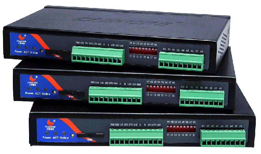 CM550-52FCM550-52X series photographView equipment
The application
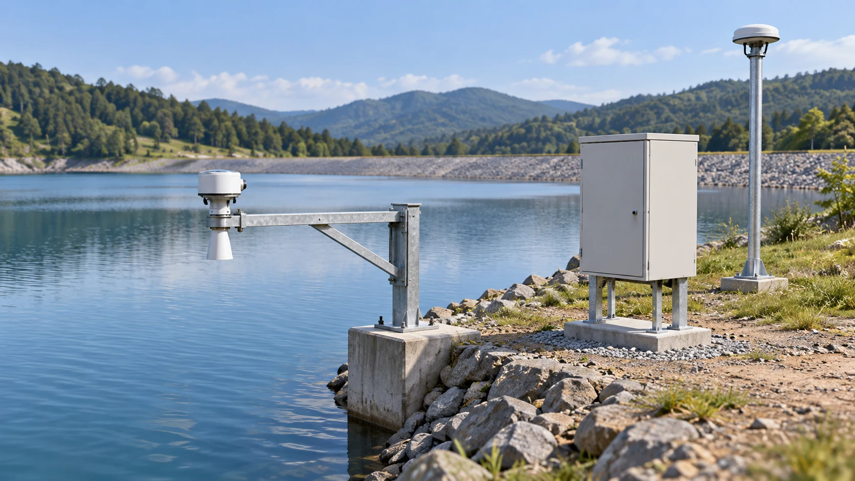
Reservoir monitoring combines readings from the water body, the dam and its surroundings. An RTU brings compatible instrument signals into a data path that operators can use to review changing conditions.
What the connection needs to solve
Measurements come from dispersed points and different instruments. The system needs to preserve the meaning of each reading and help the operator distinguish a threshold event from an instrument or communications fault.
- Connect compatible level, rainfall, flow and dam-monitoring instruments.
- Keep GNSS displacement monitoring on its separate data path.
- Assign responsibility for reviewing alerts and responding to them.
How the system connects
Follow the data path, then explore the role of each device.

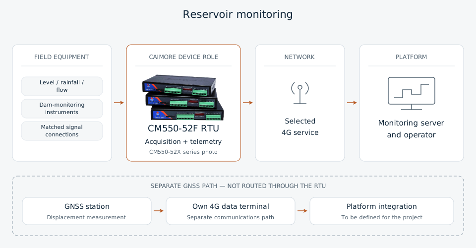
Who does what
Explore the equipment roles along the data path.
Acquires compatible signals and transmits readings.
How the data path comes together
A practical integration sequence for planning and commissioning.
Define the monitoring points
Choose the quantities and instrument locations with the responsible monitoring engineer.
Acquire instrument readings
Match instrument outputs to the CM550-52F configuration and any required acquisition modules.
Transmit to the server
Send readings through the selected 4G service and compare received values with the instruments.
Review and respond
Use platform histories and agreed alert rules; test notification and operator response before acceptance.
CAIMORE equipment for the application
CM550-52F
CM550-52F provides acquisition and transmission, with 4G, RS232 and RS485 listed in its model documentation. The photograph shows the CM550-52X series, not an identified 52F configuration.
- CM550-52F: 4G
- Documented RS232 / RS485
- Sensor acquisition and telemetry role
Before installation
Size the power supply for the instruments, reporting pattern and site conditions. Agree sampling, reporting and maintenance arrangements with the operator. Telemetry supports monitoring; it does not by itself establish structural safety or provide an automatic gate-control system.
Related applications
Discuss your equipment and data path.
Share your monitoring points, sensor outputs, site power and receiving platform. We can review the RTU configuration.